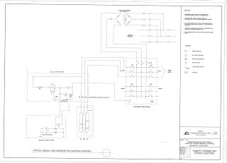
Transformer,Distribution panel & Local Control Panel all located in same location..only master control panel located 3 kms away...
from the transformer -- > distribution panel MCCB breaker(40A)-- >contactor in the local control panel
the load(LIGHT) is connected with the contactor(as mentioned in single line diagram)..
contactor is normally open..
In H-O-A when we switch to H then the contactor coil enerzise then it become closed..
then the power is supplied to load..
when we make in AUTO it check the photocell, the photocell NC in night, at night the supply goes to contactor coil and it enerzises and become NC.. then the supply goes to light..
my doubt
1) when we supply the power from the master control panel is it enough to close the relay contact (CR1 & CR2) which is located in local control panel..
2)how much voltage required 277 v relay to close its contact?
3)according to the calculation we get around 240 or 235 at the receving end after the voltage drop.. can we use 240v relay?
 Temperory circuit..
